General Information
| Model number | 1771-ID01 |
| Country of origin | USA |
| Condition | Brand New |
| Dimension | 25.4x15.2x6.5cm |
| Weight | 0.5kg |
| Lead time Warranty | in stock |
| MOQ | 1 pcs |
Core Description
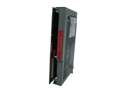
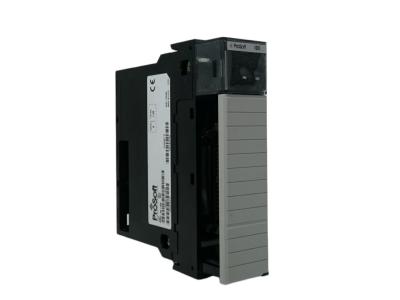
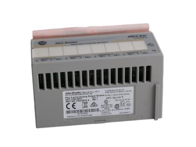
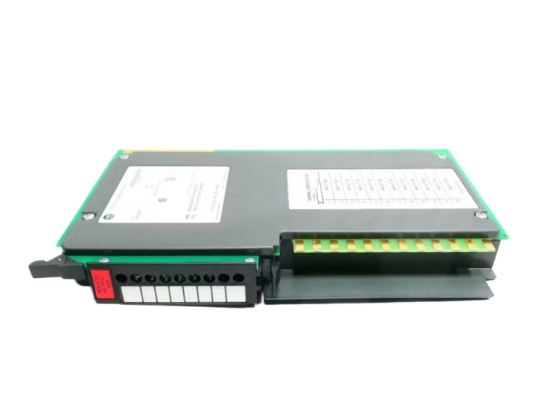
Designed to interface high-voltage field devices with industrial logic platforms, the 1771-ID01 is an Allen-Bradley PLC-5 isolated input module featuring 6 discrete channels rated for nominal 220/240V AC or 240V DC operations. It is equipped with advanced internal filtering circuitry to eliminate electrical noise and contact bounce transients, offering an operating range of 184V to 276V AC/DC. Each channel is fully opto-electrically isolated up to 1500V AC RMS, allowing direct control execution from high-voltage switches without risking cross-talk or hazardous ground loop damage back to the chassis backplane.
Specific Application
High-Voltage Interface Tracking: Monitoring heavy-duty plant floor pilot devices (e.g., industrial limit switches, float switches, selector switches, and pushbuttons) operating on 220/240V power networks.
Inter-Module Interlocking Control: Accepting direct drive signals from localized AC output modules within complex relay logic or safety interlock loops across the processing grid.
Ordering Information
|
Component Category |
Catalog Number |
Official Description |
Procurement & Application Notes |
|
Main Module |
1771-ID01 |
Isolated AC/DC (220/240V) Input Module, 6-Channel |
Main item. 6 fully isolated inputs. Operates on 184–276V AC/DC. |
|
Required Wiring Arm |
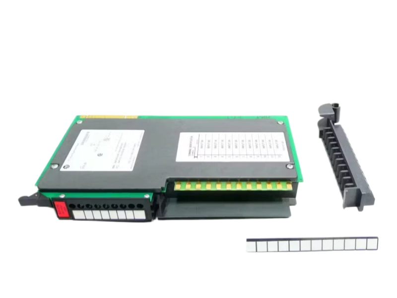
1771-WD |
12-Terminal Field Wiring Arm |
Included with module. Shipped standard; order separately only if a replacement is needed. |
|
Chassis Slot Keying |
— |
Plastic Keying Bands |
Included with chassis. Positioned between backplane pins 4-6, 14-16, and 28-30. |
|
Compatible Chassis |
1771-A1B / 1771-A2B / 1771-A3B / 1771-A4B |
Universal I/O Chassis (4, 8, 12, or 16-Slot) |
Required host chassis. Module occupies 1 standard slot (74mA backplane draw). |
|
Interfacing Resistor |
— |
3.3K Ohm, 20W Power Resistor |
Required option. Needed only if directly driven by a 1771-OM output module terminal. |
System Compatibility
Installation & Troubleshooting FAQ
Q1: What are the specific delay times introduced by the internal filtering on the 1771-ID01?
A: To limit the chaotic effects of voltage transients caused by contact bounce or radiated electrical noise, the 1771-ID01 features built-in input filtering. This filtering creates a nominal signal delay that must be factored into execution loops: for AC inputs, the turnaround delay is 20+10ms for both turning ON and OFF; for DC inputs, the delay is 10+4ms when turning ON, and 20+9ms when turning OFF.
Q2: Can I directly drive a 1771-ID01 input terminal using an AC output module like the 1771-OM?
A: Yes, an AC (220/240V) Output Module (Cat. No. 1771-OM) can directly drive the input terminals of a 1771-ID01 module. However, you must connect a 3.3K ohm, 20W resistor between the active output terminal and the L2 common line. Alternatively, a network consisting of a 100 ohm, 3W resistor and a 1µF capacitor can be used. Crucially, you must use the exact same AC power source for both modules to ensure proper phasing and prevent terminal degradation.
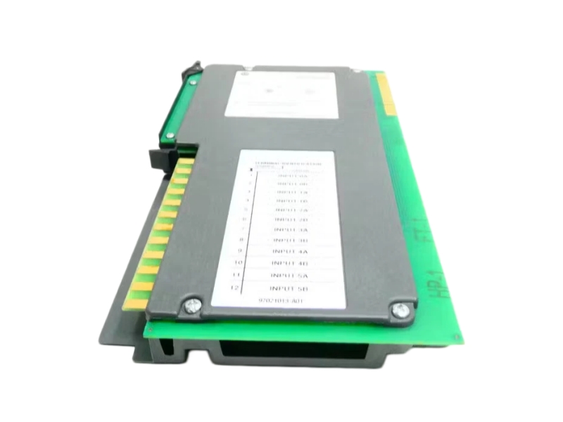
Q3: What wire sizes and physical limits must be observed when landing lines on the 1771-WD wiring arm?
A: Field connections require 2 wires per input channel, with exactly one wire secured per terminal screw. To minimize voltage drop across long field cable distances, you should utilize stranded 14 or 16 gauge wire. The maximum conductor wire size allowed is 14 gauge stranded with a maximum insulation thickness of 3/64 inch. When securing the leads, the wiring arm screws must be tightened to a specific torque of 9 pound-inches.
Q4: The 1771-ID01 module will not seat into its chassis slot during installation. What is causing this physical binding?
A: This indicates a mechanical mismatch with the backplane Keying Bands. The rear edge of the 1771-ID01 circuit board features three specific physical slots. To allow smooth insertion, the plastic keying bands on the chassis backplane connector must match these slots exactly. Ensure the bands are placed precisely between positions 4 and 6, 14 and 16, and 28 and 30. Additionally, verify you are not attempting to insert the module into the left-most slot of the chassis, which is reserved strictly for adapter or processor modules.
Q5: How do I interpret the front panel neon indicators to troubleshoot a suspected field switch failure?
A: The front panel contains 6 neon status indicators corresponding directly to inputs 0 through 5 (the top, bottom, and middle-most indicator slots are not used). A status indicator illuminates only when its associated field input is energized and drawing nominal logic-one current (3.5mA RMS @ 220V AC or 3.0mA @ 220V DC). If a field switch is physically closed but the corresponding neon light remains dark, use a multimeter to check if the field voltage at the 1771-WD arm has dropped below the module's minimum required on-state threshold of 184V AC/DC.
Contact information
Please don’t hesitate to contact us if you have any questions or concerns before or after your purchase. We are committed to your 100% satisfaction.
Sales Manager:Stella
Email:sales6@apterpower.com
Whatsapp:+86 18159889985
We provide professional global shipping services to ensure your industrial automation parts and equipment arrive safely and on time. To meet different delivery requirements, we cooperate with internationally recognized logistics companies, including:FedEx/DHL/TNT/UPS/SF Express
Whether you require standard international shipping or urgent express delivery, we can arrange flexible logistics solutions tailored to your project schedule and destination.
For convenient and secure transactions, we accept T/T (Telegraphic Transfer) payment.
After order confirmation, our sales team will provide complete payment details and invoice information to ensure a smooth and efficient payment process.
We are committed to providing efficient delivery and dependable customer service for clients worldwide.
| AB | 119524 119522 129708-01 | AB | 1326AB-B430E-21 | AB | 1336-BDB-SP34D 77101-169-64 |
| AB | 119524 129708-01 | AB | 1326AB-B515E-S2K5L | AB | 1336-BDB-SP38A |
| AB | 1203-CN1 | AB | 1326AB-B720E-S2L | AB | 1336-BDB-SP4D 74103-244-54 |
| AB | 1203-GD1 | AB | 1336-B005-EAD-FA2-L1-S1 | AB | 1336-BDB-SP5C |
| AB | 1203-GU6 | AB | 1336-BDB-SP17C 74101-482-51 | AB | 1336-BDB-SP5D |
| AB | 125760-01 | AB | 1336-BDB-SP29A 74101-169-53 | AB | 1336-BDB-SP6A |
| AB | 1305-BA01A-HA2 | AB | 1336-BDB-SP29C 74101-169-53 | AB | 1336-C003-EOD |
| AB | 1305-BA03A | AB | 1336-BDB-SP29D 74101-169-53 | AB | 1336F-B015-AA-EN |
| AB | 1305-BA09A-HA2 | AB | 1336-BDB-SP30D | AB | 1336F-B025-AA-EN |
| AB | 1305-KBA09 | AB | 1336-BDB-SP30D 74101-169-54 | AB | 1336F-BRF100-AA-EN |