General Information
| Model number | 990-04-50-02-00 |
| Country of origin | USA |
| Condition | Brand New |
| Dimension | 7.3x5x10cm |
| Weight | 0.44kg |
| Lead time Warranty | in stock |
| MOQ | 1 pcs |
Core Description
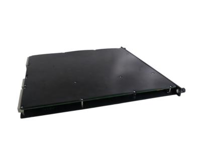
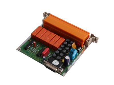
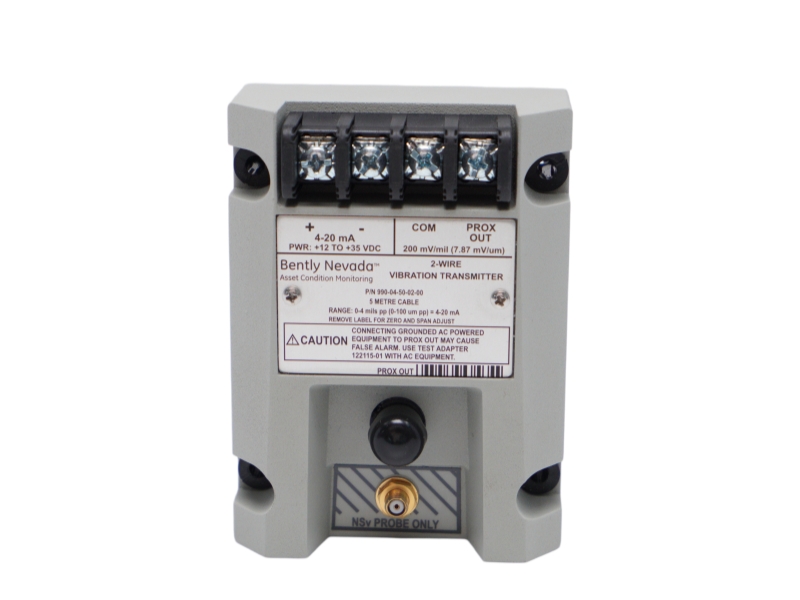
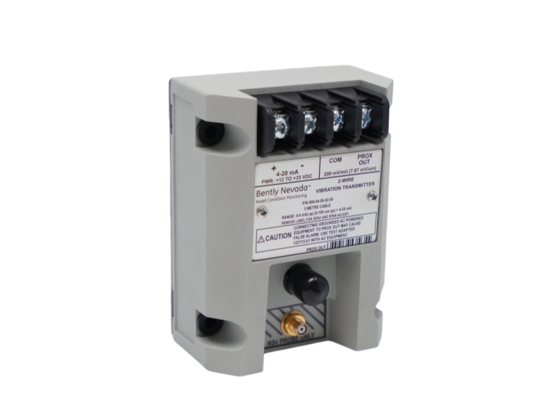
The 990-04-50-02-00 is a Bently Nevada 990 loop-powered two-wire vibration transmitter featuring a 0-4 mils peak-to-peak (0-100 µm pp) full-scale measurement option and a 5.0-meter system length pairing. Engineered primarily for original equipment manufacturers (OEMs) of centrifugal air compressors and small pumps, this bulkhead-mounted device integrates an internal Proximitor sensor layer into a potted, 100% condensing humidity-rated assembly. It conditions proximity inputs directly into an industry-standard 4 to 20 mA proportional analog signal, passing absolute housing parameters straight to machine control loops without the cost or space overhead of external drivers.
Specific Application
Ordering Information
990-AA-BB-CC-DD
990-04-50-02-00
| A: Full-scale Option | |
| 04 | 0-4 mils pp (0-100 μm pp) |
| 05 | 0-5 mils pp (0-125 μm pp) |
| 08 | 0-8 mils pp (0-200 μm pp) |
| 10 | 0-10 mils pp (0-250 μm pp) |
| B: System Length Option | |
| 50 | 5.0 meters (16.4 feet) |
| 70 | 7.0 meters (23.0 feet) |
| C: Mounting Option | |
| 01 | 35 mm DIN rail clips |
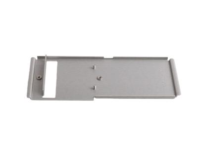
| 02 | Bulkhead screws |
| 03 | DIN clips and screws |
| D:Agency Approval Option | |
| 00 | Not required |
| 01 | CSA Division 2 |
| 05 | CSA Division 2, ATEX Zone 0, ATEX Zone 2 and includes ABS maritime approval |
System Compatibility
Installation & Troubleshooting FAQ
Q1: Why is my PLC trending loop stuck completely flat at 23 mA when using a 990-04-50-02-00?
A: A constant 23 mA output indicates the transmitter has activated its internal protection ceiling. The 990 transmitter features a built-in current limiting feature rated at 23 mA typical. This ceiling triggers when the connected loop impedance parameters are exceeded or if the external loop voltage is shorted. Check the loop wiring and verify that your total loop resistance stays strictly below the maximum linear boundary curve calculated as:
![]() Q2: Why does the analog loop output drop instantly below 3.6 mA when a technician lands a standard grounded oscilloscope on the PROX OUT jack?
Q2: Why does the analog loop output drop instantly below 3.6 mA when a technician lands a standard grounded oscilloscope on the PROX OUT jack?
A: This indicates an accidental grounding trip of the safety protection loop. The transmitter's front panel coaxial connector and PROX OUT terminal block provide a non-isolated dynamic transducer signal. Connecting grounded, AC-powered diagnostic equipment directly to this port ties the 4 to 20 mA loop return line to earth ground, activating the module’s Not OK / Signal Defeat circuit which drops the output below 3.6 mA within 100 µs to prevent false alarms. To safely pull diagnostic dynamic waveforms into AC-powered instruments, you must isolate the signal using a 122115-01 Test Adapter.
Q3: What specific calibration physical step must be completed to adjust the loop boundaries during field commissioning?
A: The transmitter features non-interacting external zero and span adjustments hidden beneath its main faceplate label. To align the loop parameters, peel back the label corner to access the adjustment potentiometers. Because these adjustments are completely non-interacting, adjusting the zero offset pot will not distort your full-scale span limit, allowing fast loop tuning using a digital multimeter and an AISI 4140 steel calibration block.
Q4: Why does the transmitter output drop to less than 3.6 mA for a brief period every single time the main instrumentation panel is powered up?
A: This is standard device behavior and does not indicate a system failure. The module contains an integrated Power-up inhibit circuit that forces the loop output to remain under 3.6 mA (the defined Not OK threshold state) for exactly 2 to 3 seconds after power is applied. This intentional delay signals to the receiving PLC or control logic that the internal Proximitor conditioning loops are still warming up and stabilizes the circuit before allowing active machinery trip signals to execute.
Q5: My 3300 NSv proximity probe keeps binding inside the casing thread before reaching its target gap distance. What is causing this layout error?
A: This physical binding indicates you have exceeded the mechanical thread engagement capacity of the sensor. For standard metric or English probe housings, the maximum length of thread engagement must be restricted to 1.5 times the nominal thread diameter (e.g., maximum 0.375 inches for 1/4-28 threads, or 12 mm for M8x1 threads). Exceeding these engagement thresholds assumes a non-matching fit class and causes the sensor threads to bind against internal casing tolerances.
Contact information
Please don’t hesitate to contact us if you have any questions or concerns before or after your purchase. We are committed to your 100% satisfaction.
Sales Manager:Stella
Email:sales6@apterpower.com
Whatsapp:+86 18159889985
We provide professional global shipping services to ensure your industrial automation parts and equipment arrive safely and on time. To meet different delivery requirements, we cooperate with internationally recognized logistics companies, including:FedEx/DHL/TNT/UPS/SF Express
Whether you require standard international shipping or urgent express delivery, we can arrange flexible logistics solutions tailored to your project schedule and destination.
For convenient and secure transactions, we accept T/T (Telegraphic Transfer) payment.
After order confirmation, our sales team will provide complete payment details and invoice information to ensure a smooth and efficient payment process.
We are committed to providing efficient delivery and dependable customer service for clients worldwide.
| Bently Nevada | 330101-00-08-05-02-05 | Bently Nevada | 330101-00-18-10-02-CN | Bently Nevada | 330101-00-28-10-02-05 |
| Bently Nevada | 330101-00-08-10-02-00 | Bently Nevada | 330101-00-19-10-02-00 | Bently Nevada | 330101-00-30-50-02-00 |
| Bently Nevada | 330101-00-12-10-01-CN | Bently Nevada | 330101-00-19-10-02-00 | Bently Nevada | 330101-00-36-10-01-00 |
| Bently Nevada | 330101-00-10-10-02-00 | Bently Nevada | 330101-00-20-10-02-05 | Bently Nevada | 330101-00-50-10-02-00 |
| Bently Nevada | 330101-00-12-10-02-05 | Bently Nevada | 330101-00-20-15-02-05 | Bently Nevada | 330101-00-50-20-02-CN |
| Bently Nevada | 330101-00-15-10-02-00 | Bently Nevada | 330101-00-20-50-02-05 | Bently Nevada | 330101-00-60-10-02-00 |
| Bently Nevada | 330101-00-16-10-02-00 | Bently Nevada | 330101-00-24-10-02-05 | Bently Nevada | 330101-00-63-10-02-00 |
| Bently Nevada | 330101-00-16-10-02-00 | Bently Nevada | 330101-00-28-05-02-00 | Bently Nevada | 330101-00-63-10-02-00 |
| Bently Nevada | 330101-00-17-10-02-CN | Bently Nevada | 330101-00-28-05-02-00 | Bently Nevada | 330101-00-75-10-02-00 |
| Bently Nevada | 330101-00-18-10-02-00 | Bently Nevada | 330101-00-28-10-02-00 | Bently Nevada | 330101-00-76-05-01-00 |